Are you ready to explore how we can help you?
Our world-class experts are available to help find answers to your toughest questions.
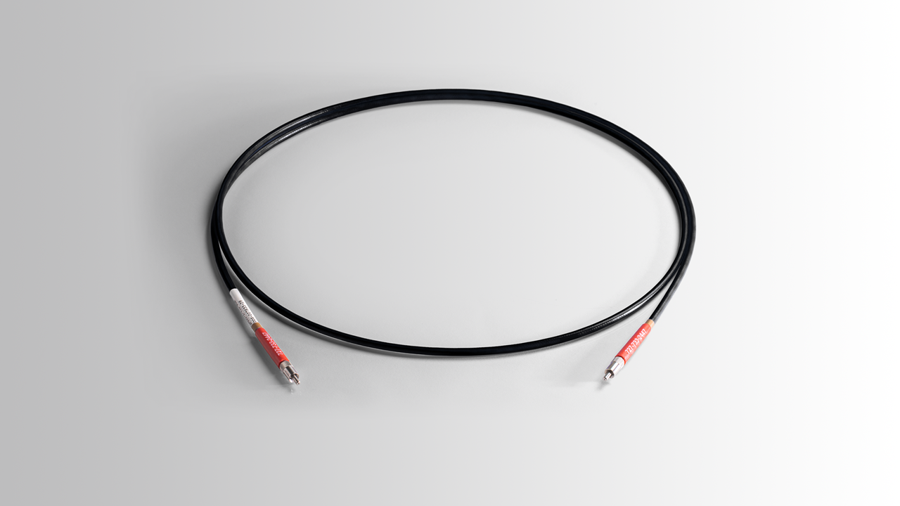
Need to know more about how our fibers work, and their properties? We’ve compiled some useful information to save you time and ensure you choose the right fiber type for your application.
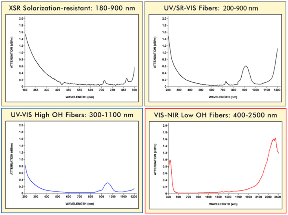
To achieve the best system performance, it is important to choose optical fibers that transmit well over your full wavelength range of interest. This will minimize the amount of light lost through fiber coupling, and reduce attenuation of some wavelengths over others. When working in the ultraviolet portion of the spectrum, particularly below 300 nm, it is important to use solarization-resistant fibers, as other fibers will become less transmissive over time at those wavelengths (an effect known as solarization).
Take a look below to find the attenuation spectrum that best suits your application, or contact one of our application engineers for guidance. Keep in mind that 1 dB is equivalent to ~21% of light being lost in transmission.
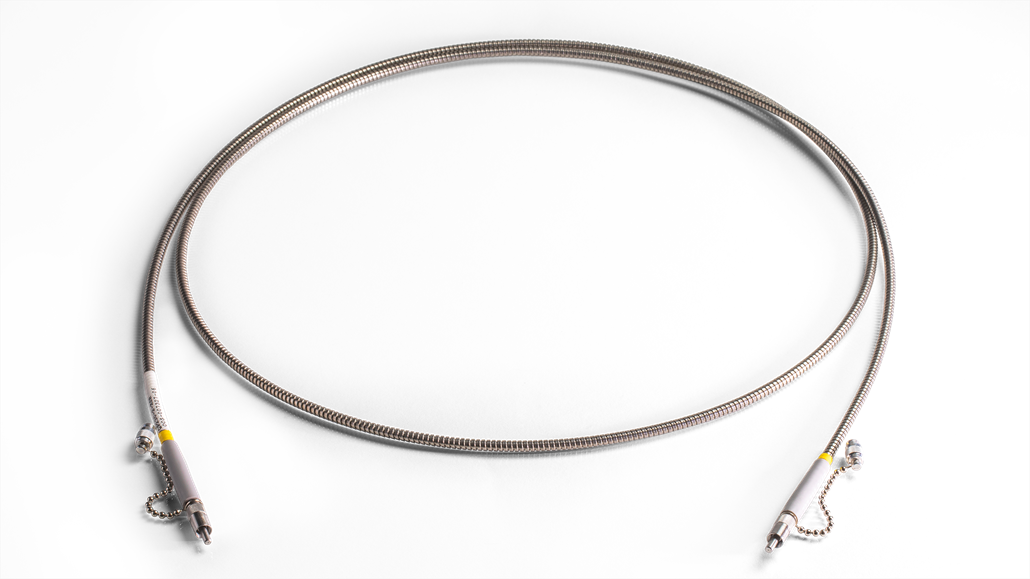
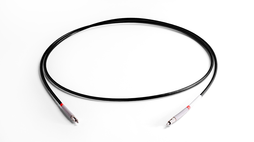
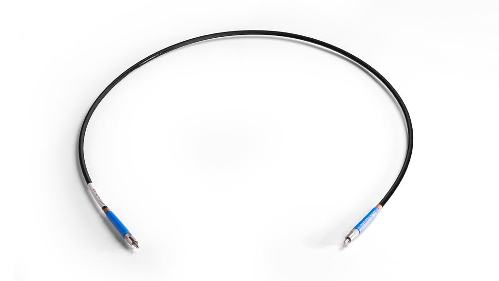
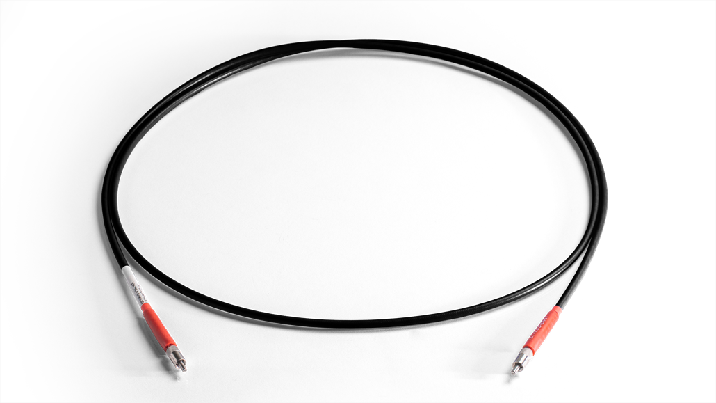
Our optical fiber and probe assemblies are clearly and cleanly labeled in three ways so that you can always determine the part number, the fiber core diameter, and its wavelength range of best efficiency.
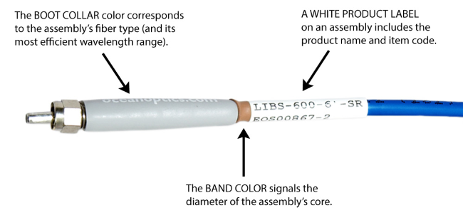
The assembly’s boot color lets you know the fiber type and the most efficient wavelength range for using your fiber.
| Boot | Color | Product Code | Fiber Type | Best Efficiency |
| Gray | -XSR | UV-VIS XSR Solarization Resistant | 180 – 800 nm | |
| Gray | -SR | UV/SR-VIS High OH content | 200 – 1100 nm | |
| Blue | -UV-VIS | UV-VIS High OH content | 300 – 1100 nm | |
| Red | -VIS-NIR | VIS-NIR Low OH content | 400 – 2100 nm |
The assembly’s color band tells you the the fiber core diameter.
| Band | Color | Fiber Core Size |
| Purple | 8 μm | |
| Blue | 50 μm | |
| Green | 100 μm | |
| Yellow | 200 μm | |
| Gray | 300 μm | |
| Red | 400 μm | |
| Orange | 500 μm | |
| Brown | 600 μm | |
| Clear | 1000 μm |
The fiber assembly jacketing is designed to protect the fiber and provide strain relief, but we have options that can do so much more. Tell us about the environment and application in which the fiber assembly will be used and we’ll help you to select the best jacketing material for the assembly.
| Jacket | Description | Outer Diameter | Chemical Resistance | Steam Sterilizable | Temperature Limit | Mechanical Tolerance | Maximum Length |
| PVC monocoil | PVC covering stainless steel monocoil; OEM applications only | 3.4 mm | Poor | No | 70°C | Good | 6 m |
| PVDF zip tube | Best for budget-conscious applications; standard in lab-grade assemblies | 3.8 mm | Poor | No | 100°C | Good | 50 m |
| PVDF zip tube (large OD) | Best for budget-conscious applications; larger in diameter than jacket #2 | 5.0 mm | Poor | No | 100°C | Good | 50 m |
| Silicone Monocoil | High-end jacketing; standard in premium-grade assemblies (silicone covering stainless steel monocoil) | 5.6 mm | Good | Yes | 250°C | Good | 20 m |
| Stainless-steel BX | OEM applications only; optional polyolefin heatshrink overcoat | 5.0 mm | Good | Yes | 250°C | Poor | 4 m |
| Stainless-steel fully interlocked BX | Excellent stainless steel jacketing; supports longer lengths of fiber; optional polyolefin heatshrink overcoat | 7.0 mm | Good | Yes | 250°C | Excellent | 40 m |
Optical fiber works by guiding light down the fiber core due to variations in index of refraction between the core and cladding. A flexible buffer material in one or more layers is then applied to improve flexibility and protect the glass core/cladding. Even with this additional coating, there are still limits on how tightly the fiber can be bent without being prone to microscopic fractures that can lead to breaks.
LTBR (long term bend radius): Observe as a minimum radius allowed for storage conditions.
STBR (short term bend radius): Observe as a minimum radius allowed during use and handling.
| Band | Fiber Core Size | Fiber Types | Cladding Thickness | Buffer Material | Buffer Thickness | Maximum OD | Operating Temperature (fiber core) | LTBR | STBR |
| 50 ± 5 μm | VIS/NIR, UV/VIS | 35 ± 0.5 µm | polyimide | 17 ± 5 µm | 155 µm | -65 to 300 °C | 4 cm | 2 cm | |
| 100 ± 3 μm | VIS/NIR, UV/VIS | 12 ± 5 µm | polyimide | 17 ± 3 µm | 155 µm | -65 to 300 °C | 4 cm | 2 cm | |
| 200 ± 4 μm | VIS/NIR, UV/VIS, SR | 10 ± 4 µm | polyimide | 10 ± 5 µm | 243 µm | -65 to 300 °C | 8 cm | 4 cm | |
| 300 ± 6 μm | SR | 15 ± 7 µm | polyimide | 20 ± 10 µm | 380 µm | -65 to 300 °C | 12 cm | 6 cm | |
| 400 ± 8 μm | VIS/NIR, UV/VIS, SR | 20 ± 3 µm | polyimide | 20 ± 7 µm | 487 µm | -65 to 300 °C | 16 cm | 8 cm | |
| 500 ± 10 µm | VIS/NIR, UV/VIS | 25 ± 3 µm | polyimide | 20 ± 10 µm | 600 µm | -65 to 300 °C | 20 cm | 10 cm | |
| 600 ± 10 μm | VIS/NIR, UV/VIS, SR | 30 ± 3 µm | polyimide | 25 ± 10 µm | 720 µm | -65 to 300 °C | 24 cm | 12 cm | |
| 1000 ± 3 µm | VIS/NIR | 50 ± 3 µm | acrylate | 50 ± 40 µm | 1120 µm | -50 to 85 °C | 30 cm | 15 cm | |
| 1000 ± 20 µm | UV/VIS | 25 ± 3 µm | acrylate | 50 ± 40 µm | 1065 µm | -50 to 85 °C | 30 cm | 15 cm | |
| VIS/NIR is multimode step index fiber with a low OH fused silica core and glass cladding (400 – 2100 nm) UV/VIS is multimode step index fiber with a high OH fused silica core and glass cladding (300 – 1100 nm) SR is multimode step index fiber with a high OH fused silica core and glass cladding (200 – 1100 nm) |
|||||||||
| Band | Fiber Core Size | Fiber Types | Cladding OD | Buffer Materials | Primary Buffer OD | Maximum OD | Operating Temperature (fiber core) | LTBR | STBR |
| 113 ± 6 μm (115 μm nominal) | XSR | 125 ± 6 µm | aluminum, polymer | 150 µm | 230 µm | -50 to 80 °C | 4 cm | 2 cm | |
| 230 ± 12 μm | XSR | 250 ± 13 µm | aluminum, polymer | 300 µm | 380 ± 20 µm | -50 to 80 °C | 4 cm | 2 cm | |
| 455 ± 22 μm | XSR | 500 ± 25 µm | aluminum, silicone, nylon | 580 µm | 1300 ± 100 µm | -50 to 80 °C | 8 cm | 4 cm | |
| 600 ± 30 μm | XSR | 660 ± 33 µm | aluminum, silicone, nylon | 800 µm | 1700 ± 200 µm | -50 to 80 °C | 24 cm | 12 cm | |
| XSR is multimode step index fiber with a high OH fused silica core and fluorine-doped silica cladding (180 – 900 nm) | |||||||||
| Band | Fiber Core Size | Fiber Types | Cladding OD | Buffer Material | Buffer OD | Operating Temperature (fiber core) | LTBR | STBR |
| 8.2 ± 0.2 μm | Single mode | 125 ± 7 µm | dual acrylate | 245 ± 5 µm | -60 to 85 °C | 4 cm | 2 cm | |
| Single mode fiber is Corning SMF-28e+ fiber optimized for telecom use (1260 – 1700 nm) Single-mode performance ceases below the cutoff wavelength of λc = 1260 nm |
||||||||
Optical fibers are designed to transmit light from one end of the fiber to the other with minimal loss of energy. The principle of operation in an optical fiber is total internal reflection. When light passes from one material to another, its direction is changed. According to Snell’s Law, the new angle of the light ray can be predicted from the refractive indices of the two materials. When the angle is perpendicular (90º) to the interface, transmission into the second material is maximum and reflection is minimum. Reflection increases as the angle gets closer to parallel to the interface. At the critical angle and below the critical angle, transmission is 0% and reflection is 100% (see figure below).
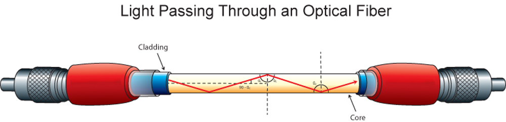
Snell’s Law can be formulated to predict critical angle and also the launch or exit angle θmax from the index of refraction of the core (n1) and cladding (n2) materials. The angle also depends on the refractive index of the media (n).
![]()
The left side of equation is called the numerical aperture (NA), and determines the range of angles at which the fiber can accept or emit light.
Most Ocean Optics fibers have a numerical aperture of 0.22 (see table below). If the fiber is in a vacuum or air, this translates into an acceptance angle θmax of 12.7° (full angle is ~25o). When light is directed at the end of an optical fiber all the light rays or trajectories that are within the ±12.7° cone are propagated down the length of the fiber by total internal reflection. All the rays that exceed that angle pass through the cladding and are lost. At the other end of the fiber, light exits in a cone that is ±12.7°.
There are many types of fibers available, with a variety of numerical apertures. While a fiber with a larger numerical aperture will collect more light than a fiber with a smaller numerical aperture, it is important to look at both ends of the system to ensure that light exiting at a higher angle can be used. In optical sensing, one end is gathering light from an experiment and the other is directing light to a detector. Any light that does not reach the detector will be wasted.
| Fiber Type | Numerical Aperture | Full Angle |
| Single mode | 0.14 | 16.1° |
| VIS/NIR | 0.22 | 25.4° |
| UV/VIS | 0.22 | 25.4° |
| SR | 0.22 | 25.4° |
| XSR | 0.22 | 25.4° |
Ultraviolet radiation below 300 nm degrades transmission in silica fibers, resulting in solarization (increased light absorption in the fiber that occurs over time and impacts data). For applications below 300 nm, we recommend solarization-resistant assemblies.
Xtreme solarization-resistant (XSR) optical fiber and probe assemblies for spectroscopy are manufactured using a proprietary process for enhanced UV transmission (signal will transmit to 180 nm) and remarkable resistance to UV degradation, making it ideal for deep-UV applications (<300 nm). Ocean Optics is the only spectroscopy manufacturer to offer XSR Fiber.
Options available
Extreme Solarization Resistant Optical Fibers (180 - 800 nm)
Prices From $216.00
Options available
Solarization Resistant Fibers (200 - 1100 nm)
Prices From $165.00
Options available
UV-Visible Fibers (300 - 1100 nm)
Prices From $157.00
Options available
Visible-NIR Fibers (400 - 2100 nm)
Prices From $153.00

Our world-class experts are available to help find answers to your toughest questions.