Making optical sensing “gettable” by providing simple, clear answers
Our world-class experts are available to help find answers to your toughest questions.
Q: How does the internal shutter of the QE Pro spectrometer operate? Is it possible to add the shutter to earlier-model Ocean Insight spectrometers?
A: The QE Pro internal shutter is controlled in OceanView spectroscopy software by activating GPIO #4 in the spectrometer. The shutter is available on newer-model, large-bench spectrometers (QE Pro and NIRQuest) and is installed at the time of spectrometer assembly. You can add the shutter later, but that incurs additional costs and time for rework.
Q: What is the thermal wavelength stability of Ocean Insight spectrometers?
A: Stability is a broad term that encompasses various elements of the spectrometer system, including the optical bench, electronics and light source. Typically, users are interested in thermal wavelength stability, which is a measure of the change in specifications (performance) at various temperatures. Stability is often expressed in pixels per °C for a passive device or as +/- °C per setpoint temperature with an active device.
We offer three primary options for maintaining thermal stability in spectrometers:
WARNING: Do not flash USB2000+ spectrometers with legacy USB2000 firmware, or permanent corruption of its FX/2 chip will occur.
Certain versions of the USB2000 (a legacy precursor to later-model spectrometers) can have problems showing up in OceanView on Windows 8.x or 10 computers. This can be resolved by upgrading the USB2000 FX2 firmware to version 2.51.0.
The firmware may need to be updated to the EEPROM in your USB2000 spectrometer. After this has been done, it will work properly on Windows 8.x and Windows 10 using OceanView software.
Please note that the firmware update has a small possibility of corrupting the EEPROM. If this happens, the spectrometer may need to be sent in for repair. This must be done in Windows. It is best to do this with no other programs running. Note: This programming process cannot be done on a computer with Windows 8.x or 10; please use a different computer with Windows 7, Vista, or XP.
Follow These Steps
Note: Do not interrupt the programming process for any reason! If the programming process is interrupted, permanent corruption can occur on the USB device. Programming will take a few minutes. IMPORTANT INFORMATION: Even if all steps are followed correctly, there is a small possibility that the spectrometer will not function after the firmware is updated and additional assistance will be required.
If the Driver is Still Not Found
If the driver is still not found after you've installed the USB Programmer and plugged in your USB2000, please try the following:
WARNING: Do not flash HR2000+ spectrometers with legacy HR2000 firmware, or permanent corruption of the FX/2 chip will occur.
Certain versions of the HR2000 (legacy precursor to the higher-performance HR2000+) can have problems showing up in OceanView on Windows 8.x or 10 computers. This can be resolved by upgrading the HR2000 FX2 firmware to version 102.0.
The firmware may need to be updated to the EEPROM in your HR2000 spectrometer. After this has been done, the spectrometer will work properly on Windows 8.x and Windows 10 using OceanView software.
Please note that the firmware update has a small possibility of corrupting the EEPROM. If this happens, the spectrometer may need to be sent in for repair.
Firmware updates must be done in Windows. It is best to do this with no other programs running. Note: This programming process cannot be done on a computer with Windows 8.x or 10; please use a different computer with Windows 7, Vista, or XP.
Follow These Steps
Note: Do not interrupt the programming process for any reason! If the programming process is interrupted, permanent corruption can occur on the USB device. Programming will take a few minutes. IMPORTANT INFORMATION: Even if all is done correctly, there is a small possibility that the spectrometer will not function after the firmware is updated.
If the Driver is Still Not Found
If the driver is still not found after you've installed the USB Programmer and plugged in your HR2000, please try the following:
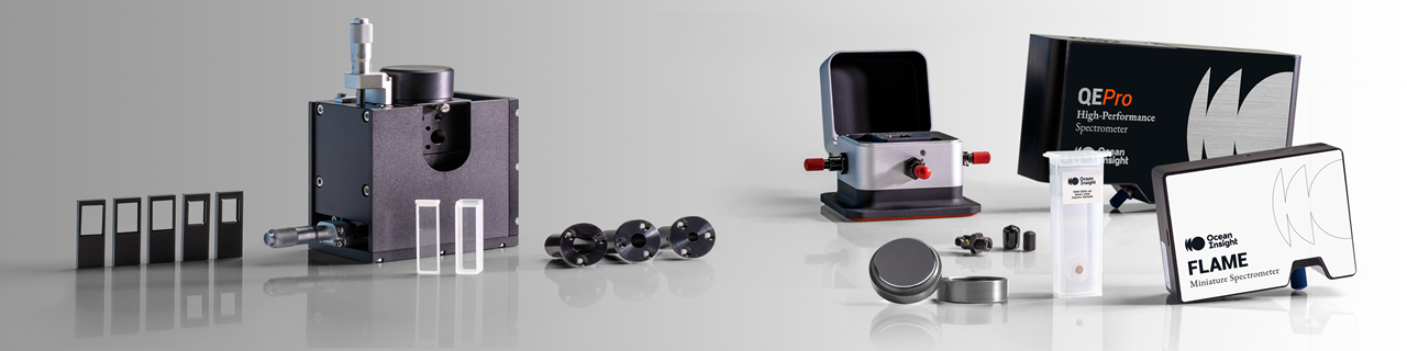
In this video, we guide you through the unpacking of an Ocean Optics spectrometer, describing the items you’ll receive and explaining why installing software is always your first step.
In this video animation, follow the journey photons take as they encounter components within the spectrometer optical bench, undergoing various processes before becoming a spectrum.
Q: When should I use an achromatic collimating lens?
A: An achromatic doublet like the 74-ACR comprises two lenses and is designed to greatly reduce chromatic aberrations. The result is a consistent FOV for the sampling setup, where “contamination” of the spectrum caused by wavelengths outside the optimal FOV is eliminated. Typically, applications including absolute irradiance benefit the most from the use of an achromatic collimating lens.
Q: Do collimating lens holder purchases include the collimating lens?
A: No, in most cases you will need to purchase lenses separately.
Q: What is the response of Ocean Insight cosine correctors?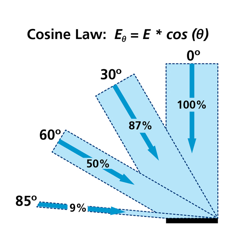
A: Our cosine correctors have 180° FOV with theoretical response close to Lambert’s cosine law, which states that the irradiance or illuminance measured will vary with respect to the cosine of the angle between the optical axis of the source and the normal to the detector. Radiance or luminance is constant in all directions.
Q: Why choose quartz cuvettes versus plastic cuvettes?
A: Although more expensive, quartz cuvettes are more durable, have better chemical compatibility, and perform better optically than plastic cuvettes. Consider:
Q: What considerations should I take when handling cuvettes?
A: There are three main areas to account for when using cuvettes:
Q: What is the “Z” dimension of Ocean Insight cuvette holders?
A: Our cuvette holders have a “Z” dimension of 15 mm, except for the legacy product USB-ISS-UV-VIS-2, which is 10 mm. Also, qpod® and qpod 2e™ temperature-controlled cuvette holders have a “Z” dimension of 8.5 mm.
The “Z” dimension is the optical height for placement of the light beam transmitting through the cuvette, and is especially important with small-volume sampling. This dimension is measured from the bottom of the cuvette to the height of ideal optical interface; your sample volume must cover this region to produce valid spectra.
Q: Why are there fittings on the base of our CUV-series cuvette holders?
A: These are internal fluid channels designed to accept a constant-temperature water source for heating or cooling of the cuvette sample. The cuvette sample will equilibrate to some level between the water and ambient room temperatures, and a thermistor or other thermometer device may be used to confirm actual sample temperature. A more tightly controlled method of temperature regulation is available with the CUV-QPOD sample compartments.
Q: What is the difference between the CUV-QPOD and CUV-QPOD-2E temperature-regulated cuvette holders?
A: The CUV-QPOD-2E has the control electronics incorporated into its body and comes with control software; the CUV-QPOD requires a separate controller. Pricing is comparable for both.
Q: How do I use the fiber optic dual switch (FOS-2X2-TTL) to monitor two samples in my spectrometer setup?
A: As the diagram demonstrates, light enters a bifurcated fiber assembly and then splits into two legs, each leg transmitting light to a sample. Light interacts with each sample and transmits through a second set of fibers, each of which connects to a port on the FOS-2X2-TTL.
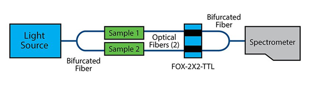
On the spectrometer side of the setup, a bifurcated fiber assembly collects light from the FOS-2X2-TLL and funnels it to the spectrometer. With the FOS-2X2-TTL in place, you can activate the shutter on either light channel to get “clean” data from each sample. An alternative is to add a second spectrometer channel to monitor the second sample.
Q: How does the fiber optic variable attenuator accessory work?
A: Fibers screw into collimating lenses on both sides of the FVA-UV, transmitting light across a metal disk into which a slit has been cut. The width of the slit varies as a function of the manually adjusted radial wheel position. Rotating the wheel allows you to vary the attenuation from the closed position (no light) to fully open.
Q: When should I use a Gershun tube?
A: Using a Gershun tube restricts the field of view of your sampling setup to a known value. Here’s an example: You’re collecting light emitted from a large projection screen in a movie theater. With a bare optical fiber, which has a 25° FOV, you may collect light from the entire screen. With the Gershun tube, you can adjust that FOV to 6°, for example, and collect light from a smaller part of the screen. This would allow you to compare spot to spot uniformity in brightness or color.
Q: Are integrated cuvette holder-light source products like the USB-ISS-UV-VIS-2 available as standalone products?
A: Yes, but you will still need to plug them into the appropriate spectrometer (Flame or USB2000+/USB4000). In addition to discrete cuvette holders and light sources, there are options with similar functionality including the ecoVis light source and CUV-FL-DA direct-attach cuvette holder.
Q: How do I use a linear variable filter for fluorescence?
A: Linear variable filters (LVFs) are useful tools for setups where high-pass, low-pass or bandpass filters are required. The filters are epoxied into slide carriers so you can move the transmission or blocking band through each filter’s wavelength range.
Where you place the LVFs is also important:
Also, LVFs can be used to reduce the stray light in absorbance measurements by limiting the illumination light to the wavelength band of interest. The LVF-HL lets you adjust both the wavelength and bandwidth of the filtering. The filter can be used either in-line or in a cuvette holder on either the illumination or read side of the holder.
Q: What reflectance standard should I use?
A: Reflectance measurements are a ratio of the reflected light spectrum to the incident light spectrum. Since there is no way to directly collect all the light incident on a surface, reflectivity is usually measured relative to a reference standard. A reflectance standard can be used to calibrate and verify your spectral reflectance measurements.
The reflectance standard chosen should be similar in reflectivity to the sample to keep signal levels about the same during measurement and ensure the best S:N. The WS-1 diffuse reflectance standard is our most popular, since it is matte white in color and is >98% reflective from 250-1500 nm (then >95% reflective up to 2200 nm). The WS-1-SL can be a good choice when working in the field or in dirty environments, since it can be smoothed, flattened and cleaned if it gets pitted or dirty.
The STAN-SSH high reflectivity specular reference standard is the best choice when measuring very shiny surfaces, but it varies in reflectivity from 85-98% over its range of 250-2500 nm. This can be accounted for in OceanView software by uploading the reflectance values and correcting for the reflectivity of the standard. This data comes automatically with the STAN-SSH-NIST calibrated reference standard (250-2400 nm). If no correction is applied, OceanView will assume the standard is 100% reflective at all wavelengths, giving distorted data.
At the other extreme, the STAN-SSL low reflectivity specular reflectance standard is best for surfaces with low specular reflectance values like thin film coatings, anti-reflective coatings, blocking filters and substrates. It has just ~4.0% reflectance from 200-2500 nm.
Q: How do I maintain my reflectance standard?
A: The black glass used in the STAN-SSL low-reflectivity standard is very durable, and the aluminum coating in the STAN-SSH high-reflectivity standard is protected with an overcoat, yet users should handle the standards with care. The surface should not be touched by hands or objects to avoid contamination and damage.
To clean the reflectance surface, first remove dirt and dust using a pressurized gas. Remove fingerprints and residual contaminants by slowly dragging across the surface a lens tissue saturated with reagent-grade isopropyl alcohol or acetone. Applied correctly, the solvent will evaporate uniformly with no streaking or spotting.
Q: How do I choose between a bifurcated optical fiber assembly and a fiber splitter?
A: Bifurcated fibers are a good choice for routing equal amounts of light from a light source to two different locations, and from a single sample to two spectrometers configured for different wavelength ranges (UV-Vis and Vis-NIR).
Fiber splitters are useful for mixing light from two different locations and delivering it through a single fiber to a spectrometer or sample. With a splitter, you can combine illumination from two different light sources, or mix light collected from two different sampling points before delivery to a spectrometer.
FIber splitters have lower transmission efficiency than bifurcated fibers due to the inefficient geometrical overlap between the fiber cores at their junction point. This effectively eliminates splitters with small core diameter fibers for most applications, as their thicker cladding diameter results in minimal geometric overlap.
Q: What core diameter optical fiber (patch cord) should I use for my application?
A: Use a smaller diameter fiber for routing high light levels, as in absorbance and irradiance measurements, and a large diameter fiber for low light level applications such as fluorescence. We offer fibers in core diameter sizes ranging from 8 µm to 1000 µm, but recommend 400 μm fibers as a good starting point for most applications.
Q: What is the field of view of standard Ocean Insight optical fibers?
A: Our fibers have FOV of ~25°. Adding an accessory like a collimating lens or cosine corrector to the end of a fiber allows users to adjust the FOV, collection efficiency and spatial resolution of their setup.
Q: When should I use an optical fiber with a linear keyed SMA 905 connector?
A: Keyed SMA 905 connectors are useful to achieve the same relative fiber orientation to the spectrometer, which can be critical for high-precision measurements or certain complex fiber designs. Additionally, patch cords with linear keyed SMAs may provide improved efficiency in spectrometers with a tall detector, such as those in the QE Pro, Maya2000 Pro, or NIRQuest optical benches.
Q: What is the different between the DH-2000 and DH-2000-BAL combination deuterium-tungsten halogen light sources?
A: All deuterium sources have an alpha line, a sharp spectral feature centered at 655 nm. This feature and other deuterium lines produce “unbalanced” output in the deuterium and halogen sources. Simply adjusting the integration time of the spectrometer to suppress the alpha line does not solve the problem as the efficiency of the system at UV wavelengths drops significantly, compromising signal-to-noise performance.
A system of proprietary internal mirrors and filters eliminates the D-alpha, D-beta and Fulcher lines in the deuterium source, producing a “smoother” spectrum across the entire wavelength range and eliminating problems associated with saturation. By comparison, most combination UV-NIR sources can be adjusted for relative intensity only.
Q: What analytes have been detected using SERS substrates from Ocean Insight?
A: We have numerous analytes with our SERS substrates using a QE Pro-Raman spectrometer and 785 nm probe, as shown in the table below. Limits of detection will vary with the sensitivity of the Raman instrument used for measurement.
|
Analyte |
Classification |
Limit of Detection |
Laser Wavelength (nm) |
|
Food & Agriculture |
|||
|
Acetamiprid |
Neonicotinoid insecticide |
1 ppm |
785 |
|
Aflatoxin B1 |
Aflatoxin |
No SERS Activity |
NA |
|
Bardac |
Insecticide |
1 ppm |
785 |
|
Captan |
Fungicide |
1000 ppm |
785 |
|
Carbophenothion |
Organophosphate insecticide |
1 ppm |
785 |
|
Carbofuran |
Carbamate pesticide |
1000 ppm |
785 |
|
Chlorpyrifos |
Organophosphate insecticide |
1 ppm |
785 |
|
Clothianidin |
Neonicotinoid insecticide |
10 ppm |
785 |
|
Coumaphos |
Insecticide |
1 ppm |
785 |
|
Crystal Violet |
Fungicide |
10 ppt |
785 |
|
Deoxynivalenol |
Mycotoxin |
No SERS Activity |
NA |
|
Dichlorvos |
Organophosphate insecticide |
100 ppm |
785 |
|
N,N-diethyl-meta-toluamide (DEET) |
Insect repellent |
1 ppm |
785 |
|
Diphenylamine |
Diphenyl fungicide |
1 ppm |
785 |
|
Fipronil |
Insecticide |
No SERS Activity |
NA |
|
Fludioxonil |
Pyrrole fungicide |
10 ppm |
785 |
|
Folpet |
Fungicide |
1000 ppm |
785 |
|
Imidacloprid |
Insecticide |
1 ppm |
785 |
|
Malachite Green |
Fungicide |
1 ppb |
785 |
|
Malathion |
Organophosphate insecticide |
1 ppm |
785 |
|
Melamine |
Food adulterant |
1 ppm |
532 or 785 |
|
Methomyl |
Carbamate pesticide |
100 ppb |
785 |
|
Metofluthrin |
Insect repellent |
10 ppm |
785 |
|
Permethrin |
Insecticide |
1 ppm |
785 |
|
Phosalone |
Organophosphate insecticide |
1 ppm |
785 |
|
Phosmet |
Organophosphate insecticide |
1 ppm |
785 |
|
Profenofos |
Organophosphate insecticide |
10 ppb |
785 |
|
Thiamethoxam |
Insecticide |
1 ppm |
785 |
|
Thiram |
Fungicide and animal repellent |
1 ppm |
785 |
|
Transfluthrin |
Insecticide |
10 ppm |
785 |
|
Tribufos |
Organophosphate pesticide |
1 ppm |
785 |
|
Trichlorfon |
Organophosphate insecticide |
1 ppm |
785 |
|
Illicit Drugs |
|||
|
Cocaine |
Stimulant |
1 ppm |
785 |
|
Codeine |
Opiate |
100 ppb |
785 |
|
Heroin |
Opiate |
1 ppm |
785 |
|
Ketamine |
Hallucinogen |
100 ppm |
785 |
|
MDMA |
Stimulant |
10 ppm |
785 |
|
Methamphetamine |
Stimulant |
1 ppm |
785 |
|
Morphine |
Opiate |
10 ppb |
785 |
|
Tetrahydrocannibinol (THC) |
Psychotropic (Cannabis) |
1 ppm |
785 |
|
Dyes |
|||
|
Rhodamine B |
Dye |
1 ppm |
785 |
|
Rhodamine 6G |
Dye |
1 ppm |
785 |
|
Ru(Bpy)3 |
Dye |
1 ppb |
785 |
|
Biologicals |
|||
|
Albumin (bovine) |
Protein |
500 ppm |
785 |
|
Albumin (human) |
Protein |
500 ppm |
785 |
|
E. coli |
Bacterium |
Unknown |
785 |
|
Glucose |
Sugar |
No SERS Activity |
NA |
|
Hemoglobin |
Protein |
No SERS Activity |
NA |
|
Antibiotics |
|||
|
Ceftiofur |
Antibiotic |
10 ppm |
785 |
|
Penicillin |
Antibiotic |
10 ppm |
785 |
|
Tetracycline |
Antibiotic |
10 ppm |
785 |
|
Miscellaneous |
|||
|
Acetate |
Salt |
No SERS Activity |
NA |
|
1-aminohydantoin HCl |
Anti-cancer agent |
1 ppm |
785 |
|
Bitrex (denatonium benzoate) |
Denaturant |
No SERS Activity |
NA |
|
BPE |
Taggant/Marker |
100 ppt |
785 |
|
Geosmin |
Flavor compounds |
No SERS Activity |
NA |
|
GtMIB |
Flavor compounds |
No SERS Activity |
NA |
|
2-methylisoborneol (MIB) |
Flavor compounds |
No SERS Activity |
NA |
|
2-naphthalenethiol |
Flavoring agent |
100 ppb |
785 |
|
Nicotinamide |
Vitamin |
10 ppm |
785 |
|
Oxalate |
Nutrient |
No SERS Activity |
NA |
|
1,10-phenanthroline |
Heterocyclic organic |
100 ppb |
785 |
|
(-)-Riboflavin |
Vitamin |
10 ppm |
785 |
|
Semicarbazide HCl |
Detection agent |
10 ppm |
785 |
Q: Are NeoFox optical oxygen sensors used for gas or liquid phase measurements?
A: Ocean Insight optical oxygen sensors are compatible in both gas and liquid phases. Dissolved oxygen measurements are critical in fields such as medical, biological, marine and beverages. While aqueous DO2 measurements are the most common, Ocean Insight oxygen sensors also are compatible in common process fluids such as alcohols, fuels and high-oxygen-capacity fluorocarbon fluids.
Since these fluorescent chemical sensors work on the principle of partial pressure, the conversion from these ppO2 values to the typical mg/L (ppm) units requires some information about the liquid system properties. This may include salinity levels and/or Henry’s coefficients to determine relative affinity of oxygen into that system

Our world-class experts are available to help find answers to your toughest questions.